Table of Contents
Intro
With the release of Cloud Native IOSXE 17.18.X, along with many things BGP support has been added for devices that can support it like the 9300 or now the newly added 9500. This is just a blog showing some simple configuration as I can’t currently find much documentation for this at the moment.
Setup
I have two switches, one is a 9300 running IOSXE 17.15.4 (LON-HQ-CSW01) and the other is a Meraki 9300 running 17.18.1 (CRG-Office-SW1). Either one has loopbacks to emulate networks, which can route between the switches. It will be a simple eBGP direct connection setup.

Configuration
On the Meraki switch, I configured a routed port with interface 172.16.100.1 on port 1/0/24. This is also now possible due to 17.18.1. There are also VRFs, but I will save this for another day. This will create an interface under the Routing and DHCP page.


While we are also on this page we will create the loopback interface 101. Loopback support was also added with 17.18.1, though seems to only support /32.

Now on to BGP, in Meraki it is under switching -> BGP Routing. First we need to create an ASN.

Next we need to add a Router, selecting the switch and applying the ASN, and a router ID which can either be a loopback or a custom one.

This will create the BGP router instance, which will then need to be edited to configure it further, such as route redistribution, neighbours and networks. I will add the loopback interface subnet as a local network.


In Meraki it seems to configure neighborships, it is all done through BGP Peer groups. I will leave it mostly default for now to keep it simple. You can configure different timers, authentication, next-hop, prefix-list in/out and as-path in/out.

Once created, we need to add the peer to 172.16.100.2 which is the other 9300 switch. You can override the peer group settings from an individual peer if wanted.

Now that should be everything! I will spare you the details for the IOSXE 9300 configuration, it will just be peering with the Meraki switch and advertising the 172.16.102.1/32 loopback network.
Results
Now in the Meraki Event Log for the switch we can see a log for the neighborship coming up.

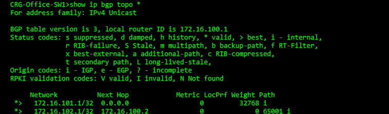
We can go further and look at the CLI of the switch to see the full neighborship and topology if wanted.


Also, as we have this CLI access we can actually see the configuration that Meraki is applying. The peer-group is configured with the as and description. The neighbour is added to this peer-group. The network we want to advertise and the activation of the peer is done in the address-family.

Then on the other switch we can also confirm we are reciving the loopback network which is configured on the Meraki switch.

And the ultimate test……a ping between to the loopbacks 🙂


Thanks for reading! I am going to spend some time playing with the different nerd knobs and see what more complex configurations and scenarios might look like in Meraki.